Introduction of Chopper
Q. Define chopper and list its applications (any three).
Q. Define chopper. Differentiate constant frequency control technique and variable frequency control technique principle.
Q. State the working principle of chopper. State control techniques used for chopper.
Q. State working principle of chopper. Describe the constant frequency system of control technique of chopper.
Q. Describe the principle of DC chopper operation. Derive an expression for its average output voltage. Q. Define chopper. List various types of chopper and state basic principle of chopper.
Definition of Chopper
- The phase controlled rectifiers provides a variable dc voltage at their output.
- An alternate way to get a variable dc voltage is to use a dc to dc converter or chopper.
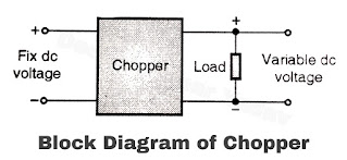
- The chopper circuits is a circuit that converts a fixed dc voltage at their input into a variable dc voltage. Hence a chopper is also known as a dc to dc converter.
- The block diagram of a chopper is as shown in Figure (a).

Figure (a) - As shown in Figure (b) chopper is basically a switch which connects and disconnects the load across the dc input supply.
- The chopper can use any switching device like SCR, power BJT, power MOSFET or IGBT. The chopper circuit using SCRS requires commutation circuits to turn OFF the SCR.
Working Principle of Chopper
- Due to the switching action the voltage across the load is a rectangular waveform. By changing the on or off time it is possible to change the average dc voltage across the load. Refer Figure (c) which shows the load voltage waveform.
- The load voltage waveform is rectangular independent of the type of load used (resistive or inductive).
- But the shape of the load current waveform depends on the type of load. For resistive load, the load current will have a rectangular shape and it will be in phase with the load voltage.
- The load current with the inductive load will be exponential in nature. The load current can be continuous or discontinuous depending on the load inductance, on time of the chopper and the magnitude of load current.

Figure (b) 
Figure (c)
Variable output voltage of Chopper
We can vary the average (dc) output voltage of a chopper by varying the duty cycle (D) or frequency of the output voltage waveform.
