Types of Solar Thermal Power Plants
In an effort to utilise solar energy for power generation, various systems are being tried.
These are :
- Low temperature solar power plant using flat plate collector.
- Medium temperature solar power plant using concentrated solar collectors.
- High temperature solar power plant using tower system.
(I) Low Temperature Solar Power System :
- The low temperature solar power plants use the working fluid temperatures in the range of 60°C to 100°C which can be obtained using flat plate type collectors or by solar ponds.
- The efficiency of such plants is only 2% to 3%.
- The working fluids used in such plants are the fluids having low boiling temperatures at atmospheric pressure.
- The fluids used are refrigerant R-11, butane gas etc.
- These systems require storage system.
(a) Low temperature flat plate collector solar power system :
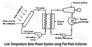
- The schematic diagram of a low temperature solar power generation system using flat plate collector is shown in Figure A. Since the water can be only heated 80°C in flat collectors, the system needs to use a working fluid having low boiling temperature like a butane gas.
- The system consists of an array of flat plate collectors. The cold water is circulated into the collector with the help of a circulating pump.
- The water gets heated in the solar collector due to solar radiations upto a temperature of about 80°C. The heated water is circulated in a heat exchanger called butane boiler, where it generates the butane gas at high pressure.
- The butane gas is supplied to a butane turbine to produce mechanical power due to expansion of butane gas. The vapour coming out of the turbine is condensed in a condenser and sent back for recirculation with the help of butane feed pump.
- The mechanical power output of turbine is converted into electric power by generator.
 |
| Figure A |
(b) Solar pond electric power plant :
- The schematic diagram using solar pond for electric power generation is shown in Figure B. The system works on Rankine cycle using R-11 as refrigerant.
- The system uses a solar pond for collection and storage of solar energy. The heat of hot brine solution from solar pond is used to evaporate the working substance R-11 at constant pressure in the boiler.
- This vapour is used to run the vapour turbine to produce mechanical power which is utilized to run a generator to produce the electrical power. The exhaust of the turbine is condensed in the condenser at constant pressure with the help of cooling water (returned from cooling tower which is not shown).
- The condensate is returned to the boiler by a pump. Thus the cycle is repeated.
- Low temperature thermal power plant are only suitable for very low power generation having very low efficiency, hence these are not used in practice.
 |
| Figure B |
(II) Medium Temperature Solar Power Plant :
- These systems employ an array of parabolic trough concentrating collectors spread over a large area. The general range of working temperatures are between 250°C to 400°C.
- Parabolic in line focusing type collectors are used and generally preferred because of low cost and require sun tracking in one plane only as compared to paraboloid concentrating collectors having higher cost and require sun tracking in two planes.
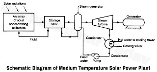
- The system works on Rankine cycle. The schematic diagram of a medium temperature solar power plant using in line parabolic trough concentrators is shown in Figure C.
- The system consists of an array of large parabolic trough collector duely installed with sun tracking device, to collect the solar radiations which is used to heat a fluid (water). This heat is transferred to storage tank and finally to feed water where the steam is generated in the steam generator.
- This steam is utilised to run a turbine coupled to a electric generator. The mechanical energy developed by the turbine is converted into electric power by the generator.
- The exhaust of steam turbine is condensed in the condenser with the help of cold water circulated in the condenser. The condensate is returned to the boiler with the help of feed pump.
- The hot water leaving the condenser is either sent to cooling tower or its heat energy can be used as process heat if the plant is used in an industry. A plant can be developed using air as working fluid instead of steam based on Brayton cycle as discussed earlier.
- A 30 MW plant have been installed in Rajasthan under the department of non conventional energy sources.
 |
| Figure C |
(III) High Temperature Solar Thermal Power Plants :
- For efficient utilization of solar heat energy into electrical energy, the working fluid has to be supplied at high temperatures. Large solar thermal plants can be built in the capacity ofSO MW to 200 MW.
- Such plants use paraboloidal dish collectors or heliostats. These systems have high thermal efficiency. Such systems are briefly discussed below.
(a) Solar thermal power plants using dish collectors :
- The solar dish collectors receive solar radiations which are collected at a common focusing point. Small volumes of the fluid are heated at this point to high temperatures.
- This heat is utilized to run a prime mover based on the Stirling cycle. A similar system has been built at Hyderabad which generates 30 kW power at about 30% efficiency.
- It uses four dish collectors in series to generate high pressure and temperature and utilizes this steam for generation of electric power in the conventional system working on Rankine cycle. Due to the limitations of size and the small quantity of fluid, dish type solar power plants are not suitable for generation of power beyond few kW for this reason such plants are not built for large power generation.
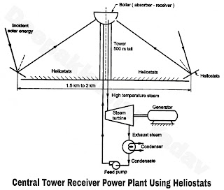
- Such plants uses central tower receiver. It uses an array of plane mirrors called heliostats which are individually controlled and tracked to reflect the solar radiations on a receiver kept on a tower of about 500 m height. Schematic diagram of a solar tower receiver power plant is shown in Figure D.
- The feed water in the absorber-receiver called boiler is converted into high temperature steam of about 600°C-700°C. This steam is supplied in a conventional steam power plant coupled to an electric generator to generate electrical power as shown.
- A thermal storage system (not shown) can be provided for use on cloudy days. A pilot plant of 50 kW was built in Itly.
- However, the plants based on the system have been commissioned in various countries in capacities 1 MW to 10 MW. The present cost of power generation is very high, it is approximately Rs. 4.6 Crores/MW.
 |
| Figure D |