Power Frequency Test of Cables
1. Power Frequency Voltage Withstand Test
Wet and Dry Withstand Test
- The test is performed in wet and dry conditions separately. Before commencement of the test, the insulator is exposed to artificial rain produced as per IS 2071 (Part 1) - 1974 for at least one minute before application of voltage and there after throughout the test. The setup in exactly similar to dry and wet flashover test
- The test voltage applied to the insulator is the specified value of the wet power frequency withstand voltage adjusted for atmospheric condition at the time of test.
- The voltage of about 75% of the test voltage is applied and then increased gradually to reach the test voltage in a time not less than five seconds.
- The test voltage is maintained at this value for one minute as per I.S. 2071 (Part II) - 1974. Two flashover at positive polarity and one flashover at negative polarity is permitted.
Power Factor Test
3. Dielectric Breakdown Test
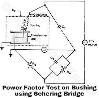
- High voltage Schering bridge is used for this test. The test setup is shown in Figure A.
- The conductor coming from bushing is connected to HV source and transformer tank is connected to detector (D) side as shown.
- The Schering bridge is balanced by usual procedure.
- The observations are taken with increasing, and decreasing values of voltages.
- The power factor (cos Φ), capacitance of bushing (C2) is evaluated for each observation.
 |
| Figure A |
 |
Figure B |
- The dielectric breakdown voltage test is performed to measure ability of an insulation (cable) to withstand electrical stress.
- With dielectric breakdown testing we are trying to answer the question "How much voltage can be applied between the wires before the insulation fails ?” The voltage is increased until the leakage current of the cable suddenly increases i.e. insulation fails.
- The highest voltage the cable can withstand before it fails is found out. Dielectric breakdown test results are significantly used during product design and qualification stages.
- If results are not satisfactory then design is modified so that insulation meets the desired performance.
- It can also be used as a type test (i.e. on a random sample can be tested) to verify that the maximum voltage causing the breakdown of the insulation is not changing drastically.
- This test is intended to find out if any defects have occurred during the manufacturing process of the insulation.
- These may include over-mold problems, spacing problems, tolerance errors in cables, or any problem that might produce arcs A high voltage of about 75% of the typical breakdown voltage is applied to the component using a dielectric tester.
- The tester monitors the amount of current continuously until the insulation fails or the time limit of the procedure has been reached.
- Thus in dielectric withstand testing we are trying to answer the question "Will this cable withstand a required voltage for a required time ?". If the leakage levels are within an acceptable range, the cable is approved for use.