Static VAR Compensation System
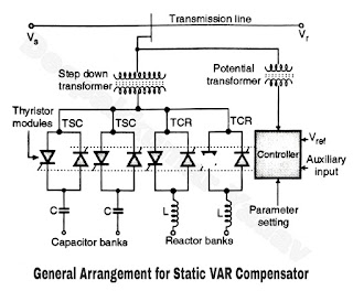
- The general arrangement of static VAR compensator is shown in Figure. VAR (Volt Ampere Reactive) is the unit for measuring the reactive power. VAR compensator is used to reduce the reactive power drawn from a transmission line.
- It shows that the static VAR compensator consists of TCRs (Thyristor Controlled Reactor) in parallel with one or more TSCS (Thyristor Controlled Capacitors).
- Due to the simultaneous use of TCR and TSC it is possible to have both capacitive and inductive compensation.
- The thyristor modules act as bi-directional static switches. A TSC is a switched capacitor and draws a leading current whereas a TCR is a switched reactor which draws a lagging current.
- The angle of lead or lag can be precisely adjusted using the thyristor modules.
- The reactive elements (C and L) of the compensator are connected to the transmission line through a transformer to isolate them from the full supply voltage. They are operated at a much lower voltage due to the use of step down transformer.
- The controller decides the exact instants at which the reactors are connected according to predetermined strategy. This will maintain the transmission line voltage at a fixed level.
- In order to achieve this the control system takes the stepped down line voltage from a potential transformer (PT). In addition to this the other input parameters or variables are also applied at the input of controller.
- The controller output is applied to the gates of the thyristors connected in the thyristor modules. It controls the conduction angle of each thyristor, to maintain the compensator voltage more or less constant.
