Procedure for Back to Back Test on Transformer With Neat Circuit Diagram & Advantages and Disadvantages of this Method
Q. Explain the procedure for back to back test on transformer with neat circuit diagram. State advantages and disadvantages of this method.
- If large transformer are to be tested for determining their efficiency, temperature rise regulation then a load of high capacity, may not be available and if available, the energy consumed in testing will be wasted.
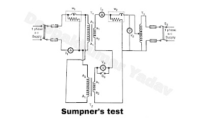
- To overcome this difficulty back to back test is adopted It is a regenerative test and hence economical and very useful. T1 and T2 are two identical transformers T3, autotransformer S1, S2 and S3 switches A-ammeters, V - voltmeters, W - wattmeters.
- Two similar transformers are required to carry out this test. As shown in Figure A the primaries of two transformers ( T1 and T2) are connected in parallel across the supply at rated voltage of primary. Their secondary's are connected in phase opposition or back to back fashion.
- An auxiliary transformar is introduced in the secondary side. When primaries of two transformers are energized by switching on switch S1, the emfs induced in secondary windings come in phase opposition.
- Since the two transformers are identical there is no circulating current in the local circuit formed by secondary's even, if primaries are energized.
- To ensure that the secondary's are connected in phase opposition, a voltmeter (V3) and a switch is connected in parallel as shown. V3 should be of the double range of that of secondary voltage.
- This is because, if the polarities are not connected in phase opposition the voltmeter may receive twice the voltage of secondary i.e. secondary voltage of first pulse secondary voltage second transformer.
- If voltmeter indicates zero it ensure that secondary's are connected in phase opposition, then switch S3, is closed.
- If voltmeter does indicate more voltage then secondary connections are interchanged.
- To circulate the necessary current one auto transformer (T3) is used in the secondary circuit as shown. Voltage is injected by switching on S2 and by varying the voltage with the help of T3 full load current is circulated the secondary's.
- The current corresponding to this circulating current also flows in the closed circuit formed in the primaries, however it does not appear in the ammeter and wattmeter W1 connected in primary side.
- So the current taken from supply side is only the total no load current of two transformers. The wattmeter reading (W1) connected in the primary side indicates total no load loss or iron loss of two transformers.
- The wattmeter connected in secondary side (W2) indicates total copper loss or load loss of two transformers caused by the circulating current.
- Since both the losses are known efficiency of the transformer can be easily determined.
