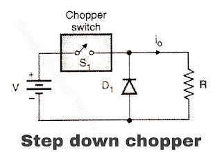
Principle of Step Down Chopper
Q. Describe step up and step down chopper with neat diagram.
Q. Describe step-up and step-down chopper.
Circuit Diagram Step Down Chopper
- The circuit diagram and the output voltage and current waveforms of a step down chopper are as shown in Figure (a) and (b) respectively. The load is purely resistive.
- When switch S1 is closed for a time TON the input voltage V appears across the load. If the switch remains off for a period TOFF, the voltage across the load is zero.

Figure (a) - Practically any power device can be used as switch These devices have a finite voltage drop ranging from 0.5 to 2 Volts but for the sake of simplicity we shall power of these neglect the voltage drops semiconductor devices, and assume the switch S to be an ideal switch.

Figure (b)
- We can vary average output voltage by using anyone of the control strategies discussed earlier.
Average Output Voltage of Step Down Chopper
Q. Describe the principle of DC chopper operation. Derive an expression for its average output voltage.
- The average output voltage is given by,
= FTON V = DV volts
- And the average load current
Q. The dc chopper in Figure (a) has a resistive load of R = 10 Ω and the input dc voltage V = 200 Volts. When the chopper switch remains on, its voltage drop is 2 Volts and the chopping frequency is 1 kHz. If the duty cycle is 30% determine :
(a) The average load voltage
(b) Rms load voltage
(c) Form Factor (FF)
(d) Ripple Factor (RF).
Soln. :
Data : f = 1 kHz ∴ T = 1/f = 1 msec, D = 30% or 0.3, V = 200 Volts and Vch = 2 Volts
Average load voltage :
= (V - Vch) x D
Substituting the values
VLdc = (200 – 2) x 0.3 = 59.4 Volts

