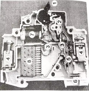
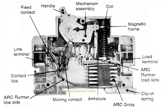
Miniature circuit breaker (MCB)
Constructional of MCB & Features of MCB:
1. Housing
2. Contacts
The contacts are made of Silver-inlaid copper which ensure longer life of contacts. These have low resistance resulting in low watt loss. The contacts are designed to have zero Bounce during closing operation.
3. Operating Mechanism
MCBs have quick make, quick break, trip-Free mechanism.
4. Mounting Arrangements
MCBs are installed directly on 35mm DIN Rail in distribution boards/control Panels simply by snap on fixing, hence save time in installation or removal.
5. Working Principle of MCB
1. B Type
For protection of Resistive loads such as bulbs, heaters etc.
2. C Type
For protection of Inductive loads such as motors, air conditioners etc.
3. D Type
For protection of Cables and highly inductive loads which have high starting current such as transformers.
Features of MCB :
- Actuator lever - used to manually trip and reset the circuit breaker. Also indicates the status of the circuit breaker (On or Off/tripped). Most breakers are designed so they can still trip even if the lever is held or locked in the "on" position. This is sometimes referred to as "free trip" or "positive trip" operation.
- Actuator mechanism - forces the contacts together or apart.
- Contacts - Allow current when touching and break the current when moved apart.
- Terminals
- Bimetallic strip.
- Calibration screw - allows the manufacturer to precisely adjust the trip current of the device after assembly
- Solenoid
- Arc divider/extinguisher
1. Housing
The housing of MCBs is made of injection molded thermoplastic polyester (PBT) in RAL 7035 Grey colors, as per international code. This material is fire retardant, Anti tracking and non-hygroscopic.
2. Contacts
The contacts are made of Silver-inlaid copper which ensure longer life of contacts. These have low resistance resulting in low watt loss. The contacts are designed to have zero Bounce during closing operation.
3. Operating Mechanism
MCBs have quick make, quick break, trip-Free mechanism.
4. Mounting Arrangements
MCBs are installed directly on 35mm DIN Rail in distribution boards/control Panels simply by snap on fixing, hence save time in installation or removal.
5. Working Principle of MCB
- Miniature Circuit Breakers are based on thermal magnetic technology. The protection is provided by combining a temperature sensitive device (bi-metal) and a current sensitive electromagnetic device.
- Both components trigger the mechanism mechanically. The MCB design is based on current limiting technology. It works by winding the live wire around a piece of iron. This makes an electromagnet. The bigger the current in the live the stronger the electromagnet.
- The electromagnet is positioned so that it pulls against a switch that can break the circuit. The switch is held closed by a spring. It's designed so that when the current is bigger than some preset value, say 20 amps, the switch is pulled open and the circuit is broken.
- MCBs are capable of handling fault levels of current up DOE to 10,000 A. However, for installations where the fault current is expected to be more than 10,000A, backup can be achieved by using Indo Asian HRC Fuse links 100A, gG type fuse link.
- MCBs have been designed to minimize energy loss through unique contact Configuration and reduction of hot spots. Watt loss per pole in Goldline MCB is far lower than that specified in IS8828:1996 / IEC pub 898-1995. Rated Current (A) Max. allowable Watt loss MCB Max. Watt Per pole as per Loss Per pole IS:8828. 1996, IEC Pub 898 (1995).
1. B Type
For protection of Resistive loads such as bulbs, heaters etc.
2. C Type
For protection of Inductive loads such as motors, air conditioners etc.
3. D Type
For protection of Cables and highly inductive loads which have high starting current such as transformers.
Features of MCB :
- DC MCB incorporates built in permanent magnet, which directs the arc in to the arc quenching chamber.
- Free from nuisance tripping caused by vibrations.
- Clear indication of polarity by the use of stickers, + sign on incoming terminal of single pole and + symbol on first pole/ - symbol on second pole of 2 pole MCBs.
- Time constant > 5ms
- DC MCB with extended terminals meeting RSD specification no. SPEC/E-12/1/04 are also available.


